What is a clash detection matrix? BIM clash matrix

See Revizto in action
Clash detection is an essential part of any modern BIM process. It is necessary in an environment that combines information from multiple project models into one centralized source of information. The primary purpose of clash detection is to ensure that no elements clash with one another. Still, if it happens, tools such as a BIM clash matrix can simplify the issue resolution process significantly.
Introduction
BIM is one of the most critical technologies in modern-day construction projects. The importance of BIM is difficult to overestimate, and many companies even assign a specific position to deal with most, if not all, of the BIM-related issues: a BIM coordinator. Working with clashes and other similar problems is one of the central tasks of any BIM coordinator. While the idea behind BIM relies on a single model that combines information from different stakeholders, it is still necessary to check for clashes in the information provided by various departments and stakeholders.
Clash detection is not a particularly difficult process in a modern-day construction project. However, it can be somewhat challenging to determine who is responsible for a clash between different models and who needs to fix it on their side. The concept of a clash detection matrix is designed to deal with precisely these issues
What is a clash detection matrix?
A clash detection matrix is a valuable clash resolution tool that can significantly simplify managing the results of the clash detection process. In most cases, clash detection and the creation of this matrix are the duties of the BIM coordinator, and they have to be performed during the project’s design phase. It is not uncommon for secondary clash detection analyses to be performed further into the project realization process to ensure that all issues are resolved or for some other purpose.
The main goal of such a matrix is to provide a relatively simple visualization framework for all the clashes and other issues found during clash detection. A clash detection matrix usually takes the form of a hierarchical table with varying degrees of complexity.
Components of a clash detection matrix
As its name suggests, a clash detection matrix is presented as an array of numbers or symbols in a specific fashion. For the sake of visualization, we can offer a somewhat basic example of such a matrix below.

- ARC represents various architectural elements.
- STR represents various structural elements.
- HVAC represents various mechanical elements and the main framework of HVAC ducts.
- PLUMB represents plumbing, smaller HVAC ducts, and other systems whose positions can be adjusted with low to moderate difficulty.
- ELEC represents electrical and fire protection frameworks, as well as other relatively minor systems with relatively low levels of adjustment difficulty.
It should be noted that none of the colors of the cells in the image above are chosen to show priority in some way. However, they are used to distinguish one category from another for better visualization.
A matrix like this can significantly simplify the assignment of priorities for all clashes and other issues found during clash detection. The precise logic behind this matrix will be elaborated upon later. Still, the most basic explanation is that the matrix showcases clashes between different groups of elements in a BIM model, and the higher the number in a cell, the higher the priority should be for fixing this category of clashes.
In the example above, we can see at least two different information groups, which we are going to go over in more detail:
- System hierarchy (colored cells).
- Coordination priority (numbers between colored cells).
System hierarchy
In the context of BIM and construction processes, a system hierarchy defines the specific categories of systems and construction elements created during construction. The base logic behind a system hierarchy creates a clear-cut list of priorities for building systems, ranging from categories that are very difficult to modify to categories that can be modified easily.
Due to the construction industry’s vast and varied nature, the specific order of the elements might differ from one category of project to another. However, the baseline for most projects should look like the following image:
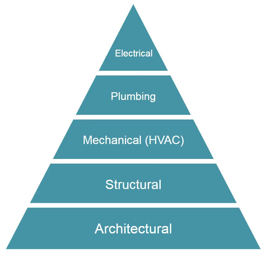
The image presents the five different groups of construction elements already mentioned in the clash detection matrix: architectural, structural, mechanical, plumbing, and electrical.
These elements are positioned in the system hierarchy in ascending order, representing the sequence in which they are implemented in a construction project. The lower the aspect is in this hierarchy, the more difficult it is to modify it to resolve issues.
Consequently, clashes affecting structural or architectural elements are commonly prioritized over the other issues. These elements are usually considered immovable. Each situation requiring the modification of any architectural or structural elements would be a significant issue that requires the involvement of many professionals, including project designers.
The next group of construction elements covers mechanical components directly correlated with specific rooms in a building (restrooms are the most straightforward example) and, thus, are also challenging to move in most cases. The primary HVAC duct also belongs to this category, primarily because of its sheer size and the amount of space it takes.
Smaller groups of objects are the next on the list, comprised primarily of smaller HVAC elements and plumbing systems. In most cases, these objects are relatively easy to modify or move, so adjusting them should not pose too much of an issue.
Despite their apparent importance, systems such as fire protection and electrical frameworks are considered the least important on this list. The main reason for this stems from the fact that these systems are comprised of smaller elements that are very easy to modify or move in the event of a clash.
Of course, the image above is not the only way to visualize the system hierarchy between construction elements. The ascending order is not set in stone, either. The only possible aspects of this logic that are difficult to modify are the correlations between the elements themselves, such as the fact that structural and architectural elements are always at the highest priority in any construction project. The logic here is that these are the most fundamental parts of any building and are extremely difficult to modify once built.
Logic of coordination priority
The numbers in the different cells of our BIM clash matrix example signify the order in which the clash detection process is performed. The process roughly follows the system hierarchy logic we discussed above. It is important to remember that each specific line in the matrix represents an entire category of objects and elements, not just a single object or system.
The red numbers signify clashes and issues between different parts of the same group of elements. Still, they cannot happen with single elements, since this would be a technical oversight instead of a clash (situations like these are also noticed and resolved a lot earlier).
The aforementioned order of clash detection checks also signifies the priority for error resolution. For example, if a clash is detected between an architectural element and a structural element, it must be resolved before any other operation is done within the clash detection department.
In some cases, the entire clash detection process can be stopped if an error is found this deep in the priority order, purely because of how the resolution of a high-level clash might modify a significant portion of the existing geometric parameters within the project. It is not uncommon for the entire clash detection process to be initiated a second time after some of its most significant issues have been resolved.
The same logic applies to the rest of the matrix, albeit with slightly less drastic measures. The lower the number in the cell, the higher the priority of the issue detected during the clash detection process.
It should also be noted that the priority logic serves another vital purpose: identifying which branch or stakeholder is responsible for fixing the issue. Due to the nature of the system hierarchy, the most moveable element of the clash becomes accountable for solving it.

In the example above, we can see that not only is the Mechanical – HVAC stakeholder responsible for solving clashes between its elements, but it is also responsible for resolving issues between HVAC and structural or architectural elements (highlighted in blue). The fact that HVAC is the most flexible of these three groups of construction elements is the main reason it will resolve issues in all three categories.
How can a BIM clash matrix assist BIM coordinators?
The matrix might not seem very valuable. Still, it can be a handy tool in the right hands, especially after being populated with information gained from the clash detection process (some clash detection solutions should be able to form groups of issues by themselves, while others might require manual input).
Being able to read and interpret a clash detection matrix is just as important as being able to create one correctly. An adequately generated and information-rich BIM clash matrix can assist with the following tasks:
- Direct association between clash groups and responsible disciplines dramatically simplifies the process of assigning clash resolution tasks in each situation.
- Easy visualization of clash priorities to understand what issues should be resolved first and foremost.
Creating your own clash detection matrix
A BIM clash matrix is an incredibly valuable tool, but it might seem too generalized, especially for large and complex construction projects. In these cases, many BIM coordinators use what is called a “detailed clash detection matrix.”
Detailed clash detection matrix
The primary purpose of a detailed clash detection matrix is to elaborate upon the original matrix with more detail about each category of elements. These matrices use each element in all the clash groups (the ones relevant to the project in question) to better visualize which elements clash.
We can take a theoretical example of a clash between a plumbing system and a structural system (number 9 in the example matrix above). In our case, we will not use all possible elements of either system; instead, we will focus on only three of each for the sake of visualization.
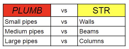
As you can see, we have broken down our groups of elements into specific elements to simplify the identification what exactly clashes with what. This kind of detailing can be performed for particular clash “cells” or for entire clash detection matrices (even if it does make them more challenging to read). We are not going to show the whole table in its detailed form, primarily because of the readability problems, but we can show how part of it is going to look:

You can see here that each large category has several subcategories for each construction element. Clashes between elements are also much easier to visualize now, so we have changed them to decimals to showcase that they still belong to specific priority groups.
A detailed clash matrix is most effective when used in large and complex projects that require a very precise level of control. Many highly specialized structures, such as medical buildings, rely on detailed matrices to ensure that the specialized equipment does not interfere with itself in different ways to ensure proper operation post-construction.
Drawing a clash detection matrix
Creating a clash detection matrix requires substantial preparation beforehand and a lengthy information management process after the matrix is complete. While some parts of the process might differ from one case to another, there is a general framework of sorts that works in most situations:
- Define the scope of the project to determine which elements and objects will be included in the clash detection analysis. Remember that it is not necessary to perform such analysis on the entire structure at once.
- Identify which categories of clashes you expect to encounter beforehand to facilitate and speed up targeted issue resolution efforts.
- Establish proper tolerance limits for each category of clashes. There are three types of clashes, and only one is a “clash” in the literal sense of the word.
- Initiate the clash detection process using either separate clash detection software or a feature in your BIM solution. Most of these systems operate similarly and usually differ the most in the feature set that comes alongside clash detection capabilities.
- Document the information gathered during the clash detection process manually or automatically. This information may include the location of a clash, its severity, and the party responsible for resolving it.
- Assign clash resolution responsibilities and monitor them to completion. A clash detection matrix can be an excellent tool for tracking the current status of such clashes.
A clash detection matrix with all this information should be reviewed regularly with other project teams to ensure that the resolution is in progress and that the issues found during clash detection are resolved in time.
Revizto and clash detection
Many modern-day BIM software applications offer substantial clash detection capabilities, intelligent clash grouping, and other valuable tools. These features can benefit BIM coordinators by simplifying the work required to export information from the software to the matrix manually.
Revizto is one such software application that offers extensive control over both the clash detection process and information processing afterward. Here are some of its most common capabilities:
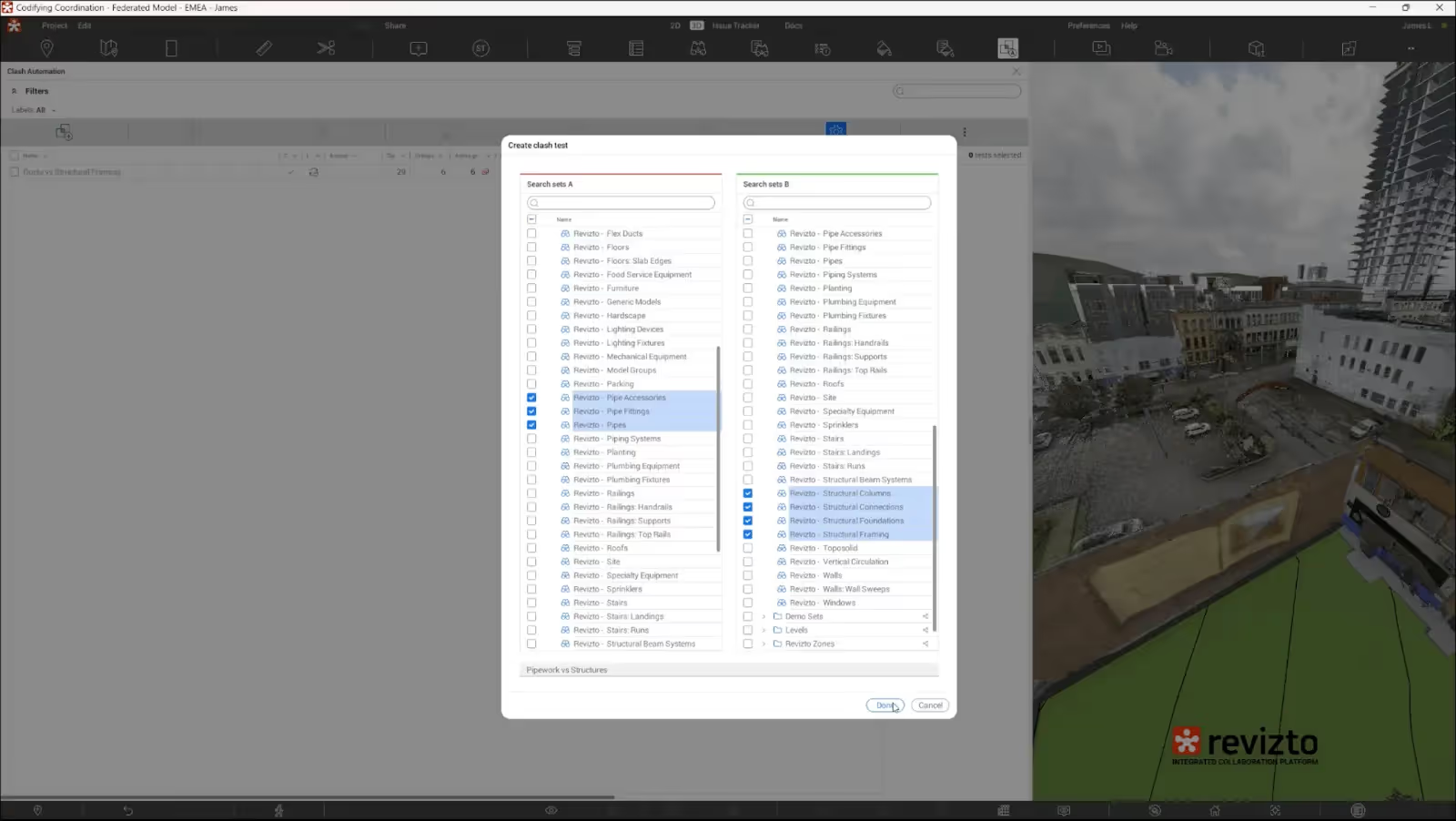
- The ability to choose specific groups and categories of project elements for which to run clash detection.
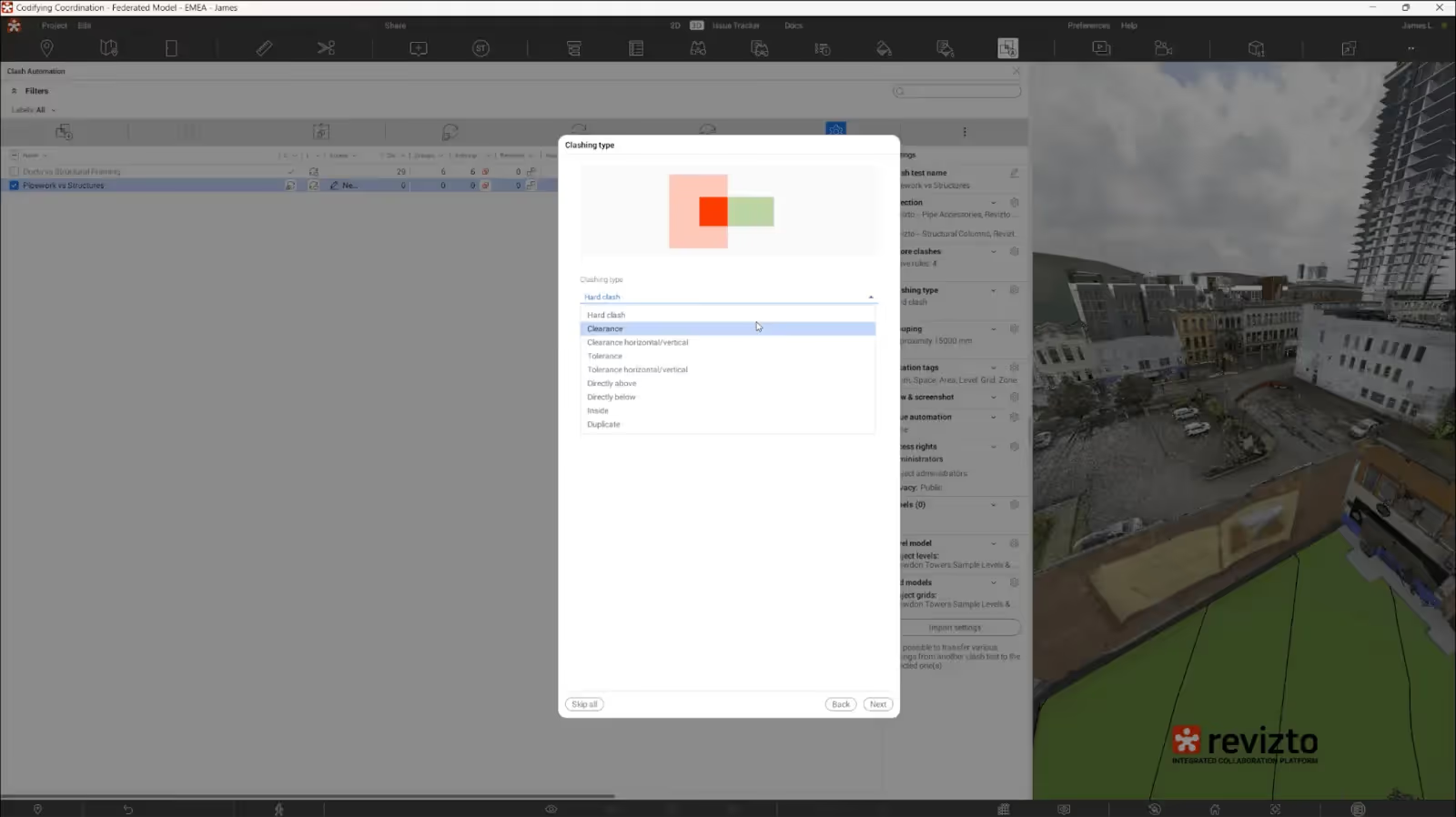
- The ability to choose specific types of clashes to be found.
- The option to add manual customizable groupings for clashes based on proximity, room, area, level, etc.
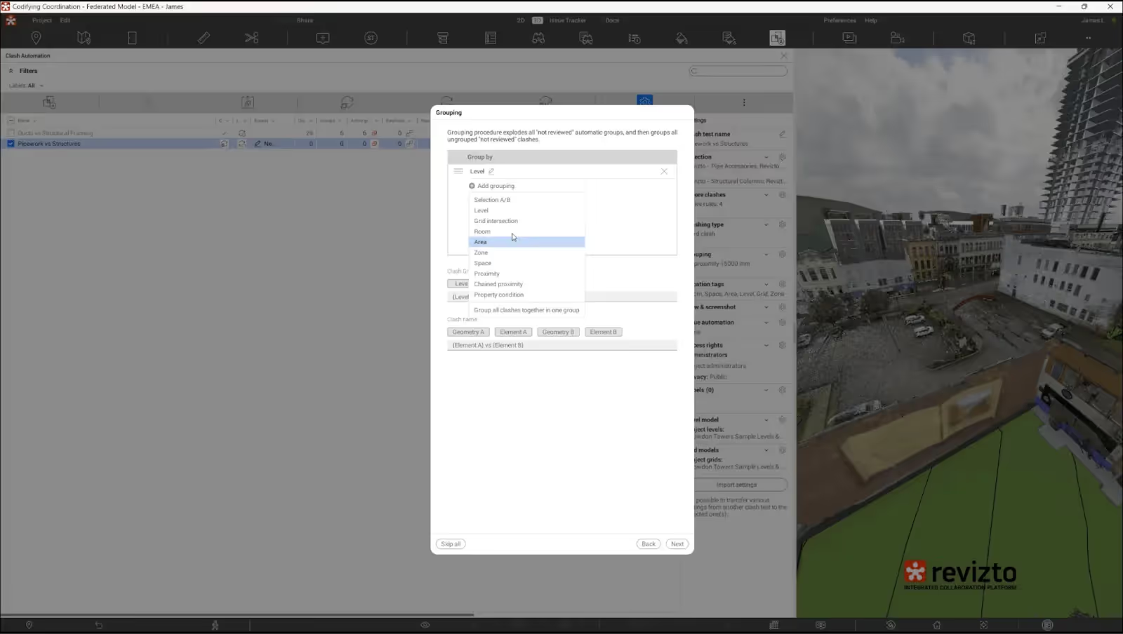
- The built-in issue-tracking capability also automatically updates the results of clash detection and allows users to perform multiple other actions, such as setting deadlines, assigning those responsible, prioritizing, and tagging.
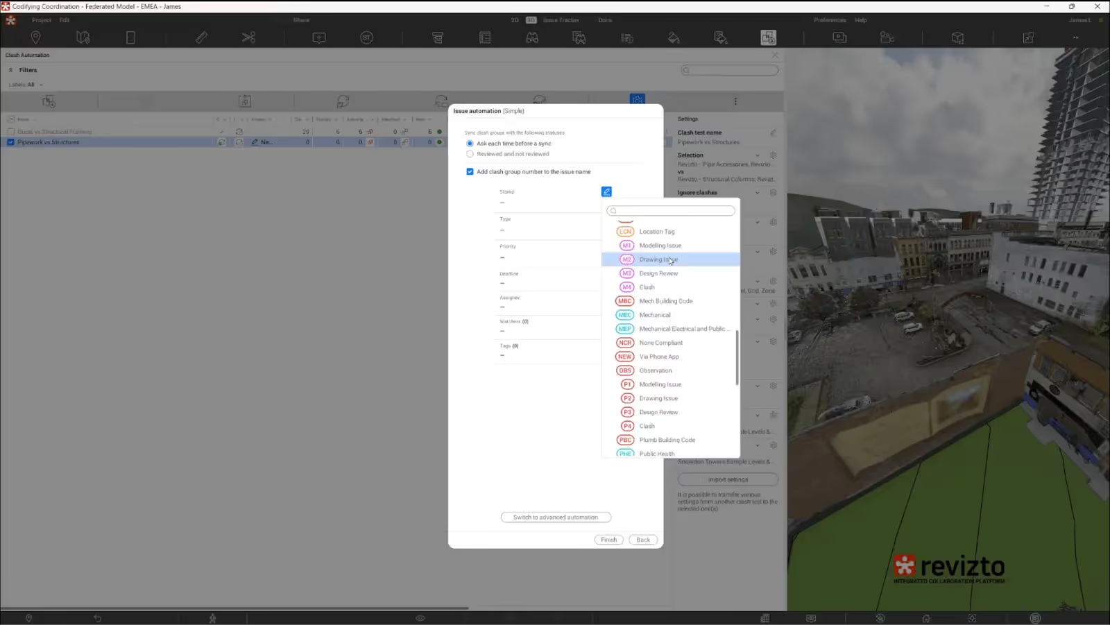
- Separate clashes can also be reviewed manually afterward and imported to the built-in issue tracker.
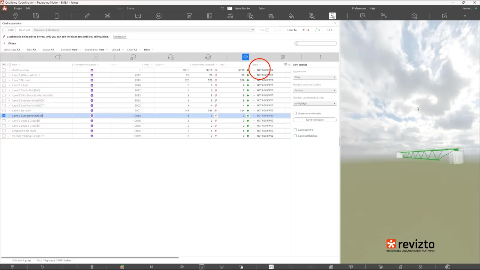
- Each clash can be reviewed separately using the project model itself.
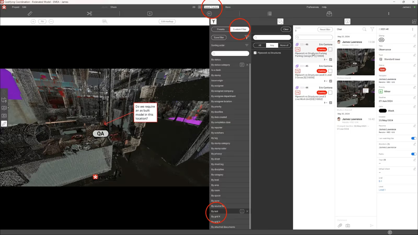
All in all, it is easy to see how using software with clash detection and issue tracking capabilities, such as Revizto, can greatly simplify the process of analyzing the results of clash detection.
Conclusion
It is essential to mention that both the “system hierarchy” and the “clash detection matrix” are just concepts, not rules or industry standards. As such, it is not uncommon for both concepts to change and adapt according to each situation. The important idea in this information is that a BIM clash matrix is a tool that can be modified to suit the needs of its user, not the other way around.
We should also say that a clash detection matrix is not the definitive method of resolving clashes. It is easy to see how some people might treat it as inconvenient, especially considering how massive the matrix will get in larger projects. Luckily, plenty of other options are available in this industry, such as using a heatmap to visually identify the most problematic locations before focusing your clash resolution efforts on these areas.
The main goal of this article was to introduce the concept of the clash detection matrix and its nuances. We hope that our efforts in this regard have been successful, since we have managed to showcase not only the definition and primary purpose of BIM clash matrices but also some examples, internal concepts such as the system hierarchy, and even the process of creating your own clash detection matrix for a specific construction project.