


View Ranges and Revizto, What’s The Big Deal?
Table of Contents

Lewis Guy, Captain Awesome and Implementation Service Manager
Never Overlook the Fundamentals
From 2007 until 2017, I spent pretty much every day of my working life inside a Revit model. I loved it, and I knew my way around even the dirtiest, darkest corners of it. But often, it is not these dark corners that catch you out. Often, it is the basics that are overlooked and cause far more significant problems than one could imagine.
Apart from the fact that the title of this blog clearly suggests what I am going to be talking about I could easily be referring to Shared Coordinates. But I am not. I am talking about “View Ranges”. Now, honestly, when was the last time that you thought about the view range in your project? How many of you have the view range set in your template? How many of you even bother to review this on your project? Don’t worry; you are not the only one. I certainly fell foul to this far too often. But I never really considered the knock-on effect that my view range could have on my drawings. Nor did I consider how this would affect my Revizto project either.
View Ranges in Revit
Within Revit, setting up a view range is easy and usually already set up in your project template. Your Company or Team CAD/BIM Manager knows what they are doing and as such the template they have spent weeks developing and updating with each yearly release of the software is going to be correct. So I don’t need to actually do anything, right?
Let’s say that is the case and you use the view ranges determined by the template. What does this actually mean?
Typically, the Top and Bottom range and the Cut Plane will be set the same for every level of your building. Below is an example of this. “It looks fine”, “It’s what we always use” I hear you say. But is it fine?
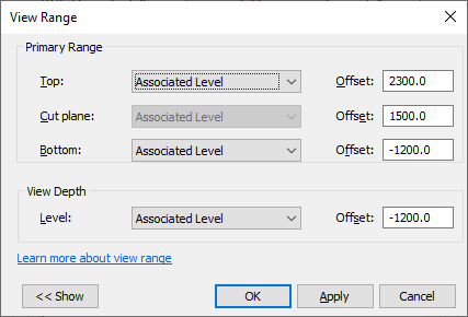
The image above shows you the view range in a section so you can see what area of the building vertically is picked up by the plan view. The Top is +2300mm, the Bottom is -1200mm and the Cut Plane is +1500mm. Based on this information I know that my plans are going to look good. I am going to see everything that I need to see, including where the windows are because my Cut Plane is high enough to pick this up. So I am happy.
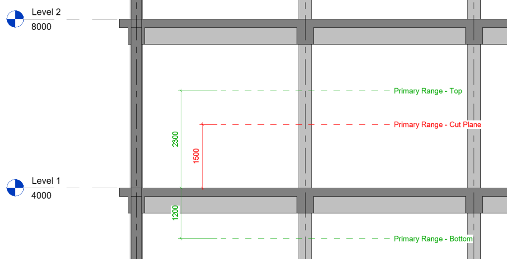
But have you ever put the view ranges together across multiple floors to see how well it really stitches together? The image below shows in section the view range duplicated across multiple floors. And straight away I can see an issue, there is a gap between the top of the view range for Level 1 and the bottom of the view range for Level 2.
In this scenario, it’s only 500mm but when you consider that the cut plane is the point at which information is shown on the plan there is actually a 1300mm gap on your drawings. 1300mm where anything drawn in that space is not visible on a plan view. 1300mm where a QS using the drawings to cost the project has no idea what is there. 1300mm that effectively doesn’t exist.
You also need to remember that the view ranges are not particularly dynamic so if the storey height changes between levels the gap distance between floors could decrease but it could also increase and even more of your building will be missing.
This is why it is so important to review the view range not just on every project but also on every floor to make sure that you don’t have gaps. Whilst not all projects will suffer from this problem you also don’t want to be the person who has to explain that 1300mm vertically is missing from every floor of your project.
Lewis Guy
14-year BIM/VDC Expert
So, How does the View Range From Revit Affect Revizto? Lets take a look,step-by-step.
How the view range is set up in Revit has a significant impact on the way the 2D information behaves in Revizto.
Firstly, we have the 2D/3D overlay.
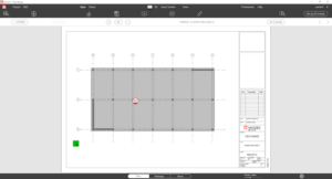
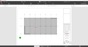
Everyone knows that if the 2D drawings have been exported from one of our Native Modelling Software Plugins then we have the ability to automatically overlay our 2D drawings into the 3D view. This function is completely driven by the view range. Here, we click on the ‘green icon’ to overlay the 2D Drawing.
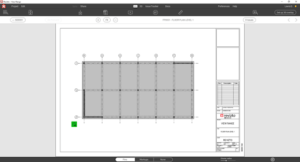
This automatically overlays drawings into the 3D space (such a useful function of Revizto, allowing you to review 2D drawings but with the context of the 3D model turned on around you)
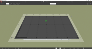
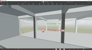
When we rotate the view we can see that the 2D overlay is sitting above the level it represents. This is because the overlay takes place, not at the reference level of the drawing but rather the cut plane.
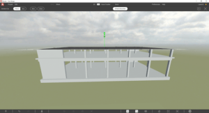
The cut plane for this drawing was set at +1500mm.

And that is exactly where the overlay has placed the drawing, 1500mm above the slab.

Secondly, and more importantly, it affects where Issues/Stamps are placed in the model and whether an Issue/Stamp shows up onto the drawing.
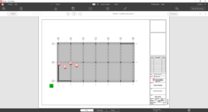
If we place an Issue/Stamp directly on to the 2D drawing where is it located in 3D? Here I have placed a Stamp referenced 1.A on to the drawing sheet.
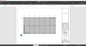
When we view this Stamp in 3D it has placed it at the Cut Plane level (+1500mm). For the most part, this is not a problem. It is close enough to the slab that I can work out what the issue is referring to though this can sometimes be an annoyance for the user, especially as (at the time of writing this blog at least) it is not possible to adjust the location in 3D of an issue raised in 2D. I can adjust its X and Y location in the plan view but I have no control over its Z location.
The reason that this is not a major concern for most people is that, more often than not, Issues/Stamps are going to be raised in the 3D model and then viewed on a 2D sheet.
So let’s take a look at how that works;
Below, I have placed 3 Stamps, all referenced 1.B at 3 different height locations. I have overlayed the view range section for context. Of the three Stamps, 1 is located at the slab level, 1 is located just below the top view range and 1 is located just above the bottom view range.
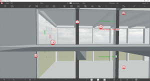
As you can see below, all 3 of the 1.B Stamps displays on the same 2D drawing. This means that the Top and Bottom levels of the view range define the boundary of the drawing. Anything placed within that boundary will be referenced on that specific 2D Drawing. That is exactly what I would have expected and wanted to happen.

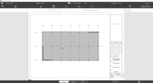
I have now placed 2 more Stamps, 1.C and this time I have placed these above the Top plane and below the Bottom plane. And I am sure you can all figure out where this is going…
On my 2D Drawing, I do not see the 1.C Stamp because they are placed outside of the boundary of that drawing.
The 1.C Stamp placed below the Bottom range is displayed on the drawing of the level below
And the 1.C Stamp placed above the Top plane shows on the drawing of the level above. Again, exactly what you would expect to happen.
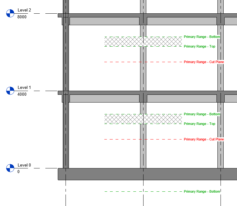
Now, let’s think back to the 500mm missing between the Top plane of Level 1 and the Bottom Plane of Level 2. The area is shown hatched in the 3D view below.
I have placed a Stamp, referenced as 1.D in the “dead space” between the view ranges for the drawings.
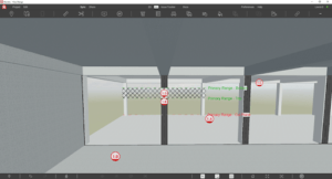
This Stamp does not show up on the Level 1 drawing

And neither does it show up on the Level 2 drawing above.
What this means is that the “dead space” of the view ranges is truly a dead space when it comes to placing Issues/Stamps in 3D and Revizto being able to locate it on to a drawing sheet.
When you think about this, it is to be expected because Revizto has to set the boundary somehow and using the view ranges is a good option for this because it is user-defined to match the setup of the drawings. But as with anything that is user-defined, user error can occur. Don’t be that user! Spend 30 minutes at the start of a project and 5 minutes every couple of months reviewing every floor level to ensure there is no “dead space” because you don’t know what exists in the space, no one does.
I bet you haven’t thought about view ranges for this long before?
This blog post came about after a discussion with a customer who was trying to set up a coordination view for Revizto and was having difficulty figuring out why certain Stamps weren’t showing up as expected on certain plan views. This led me to produce the original section drawing that showed how the view range is defined and this led me on to building a model just for this purpose.
In doing so, it made me think about view ranges for longer and harder than I had in a very long time. It made me think about how something that exists on every Revit project is so often overlooked. But imagine I told you that 1300mm had been missed horizontally from every drawing. You would first laugh, then look at me confused and then ask me if I was serious and how something so blatantly obvious could be missed. I would initially be embarrassed but then I would think about it, think back to all my previous projects where I had used that template to generate my drawings. I would then think about all of my colleagues that also use that template on their projects. I would inhale and then loudly exhale. I would probably say f**k under my breath. But one thing is for sure, I certainly wouldn’t leave the view range to the template on my project every again!
N.B. I plan on producing a guide for all of the software that we can export directly from and outline how the other tools work with their equivalents to view ranges. Most likely this will be published as another blog. Please bug me if you cannot find this and enough attention will certainly encourage me to get that finished.
About the author

Lewis Guy is a 14-year Construction Industry veteran from the UK and was a Revit Modeller and BIM Lead/Manager for years. He played a major role in overseeing Rambolls UK’s switch from Microstation to Revit and led Ramboll UK’s BIM Team and was the UK Lead of Ramboll’s Global BIM Coordination Team, and has worked on multiple, iconic global projects like the Al Rayyan Stadium for FIFA 2022 World Cup. At Revizto, he Focuses on strategic placement of Revizto within various industry workflows for client-specific needs, as well as helps train and document processes for each client.

